Showing posts with label trailing arms. Show all posts

Thursday, June 28, 2012

Rear Brake Line Brackets

Time for brake lines
With the engine nearly done and ready to go back in the car, it was time to turn my attention back to the chassis.  For one thing, I can't put the engine back on to the chassis until I put the car back on its wheels and tires.  And I can't do that until I clean and paint the wheels.  I also have to buy some tires, and for the time being, I am out of cash, so that will have to wait.

In the meantime, there are plenty of things that I can work on that won't cost me anything and don't involve the engine.  Like the rear brake brackets, for example.

These brackets don't exist.  Or at least, they didn't until I fabricated them.  The reason I had to make them was because I installed a set of disc brakes on the rear, where the standard drum brakes had been, so the brake line configuration had to change.

In the old arrangement, the rear brake lines consisted of two parts: 1) a soft, flexible hose that went from the hard line junction on the chassis to a bracket on the trailing arm; and 2) a hard stainless steel brake line that went from that bracket/hose connection directly into the brake cylinder on the drum housing.

With the drum brake removed, the configuration became much more complicated because the disc brake has a flexible line coming out (instead of a hard line) and it emerges from the back and bottom of the caliper set, which is about eighteen inches longer than the original distance.

So now I have a double hose (consisting of a long and a small piece) and no place for that hose to connect to the hard line.  In words this sounds confusing and even in 'real life' it was not much easier.  I scratched my head for months after installing the calipers, figuring I would just have to figure it out when the time came.

Tapping the hole on the trailing arm
Well the time had come.  I looked carefully at the trailing arm and discovered that there were two small holes in it just at the point where the big rubber stop (which prevents the trailing arm from hitting the body with too much force) is mounted.  I realized that if I tapped one of those holes, it would be the perfect place to mount the bracket.

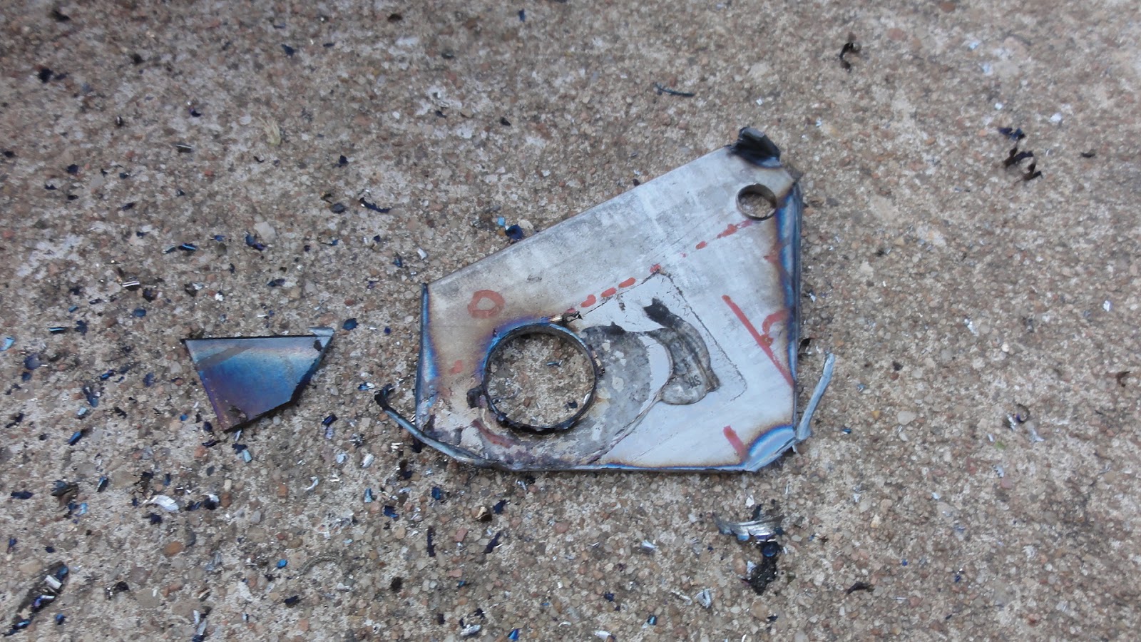
Now, the bracket has to have two holes in it.  One is large enough to allow the hose connector to pass through, but not large enough to allow the whole hose through.  Once the hose connector is in this hole, the bracket clip slides down into a slot between the bracket and the connector.  The other hole is small, used for the mounting bolt.  The whole thing can't be very big or it will get in the way, and it can't be too flimsy or it will bend and the brakes will fail.

The first prototype out of paper
Drilling the first hole
I started out with a piece of paper.  I drew what I thought would be the correct shape and cut it out.  Amazingly, my very first paper piece looked like it would work, so I set about to make it in steel.  I had a very thin piece of steel that I used to practice my welding on.  I bought it from a scrapyard, thinking it was about the same thickness as the sheet steel in the body, but it proved to be much thinner than that, so I set it aside.  Now it seemed like it would be just the right thickness, so I traced the paper template on the steel sheet and cut it out with a a high-speed cutting tool.

Several versions were required
Step drill bits that almost worked
One of the very first problems I encountered was the size of the big hole.  I measured the connector and  found I would need a hole no smaller than 9/16.  This meant I would have to buy a special bit of that size, since 1/2 inch was the largest bit that I could find in a reasonably priced set.  A 9/16 bit cost over $15, which is at least double what a new set of carbon-tipped bits (with sizes ranging from 1/16 all the way up to 1/2 inch) would cost.  And I only needed it to drill two holes.

Version #4
The compromise was to buy a step-bit set for about $8.  This three bit set looks like a stepped cone, and the idea is that it will drill holes of any size, one step at a time.  You start small and gradually the hole gets to the size you need.
The hole is first

This is the idea, but in practice, the bit heats up and fails as you get into the larger sizes, rendering the bit useless long before even one hole of the proper size has been drilled.  Eventually I decided to go ahead and buy the carbon-tipped set that included the 1/2 inch bit and use that and a file to get my 9/16 inch sized hole.

The piece is cut out
The raw piece
Compounding the bit problem was the fact that it turned out that it wasn't just to drill two holes.  Because I was going to have to fabricate several brackets as I honed in on the correct size and shape, it meant that I was going to have to drill a bunch of these big holes and the drill bits just couldn't keep up.

Eventually, however, I managed to make two holes of the proper size, but first I had to cut out, shape and bend at least five different versions of the bracket before I had one that I knew was going to fit and not fail.

Mounted, #4 is too big
Starting on #5
One key factor was the thickness of the steel.  I bought a piece of steel at Home Depot for about $9 and even though it was a lot thicker than my first piece of scrap steel, it was still too thin.  I couldn't find a piece of steel at Home Deport that was any thicker, so I settled on using a bit of the thinner steel as a shim.

Both raw brackets and shims
The bracket and shim in place
This meant cutting out two small squares of thin steel, drilling 9/16 inch holes in them, then placing those shims on the bracket with some epoxy.  Though complicated, actually worked, and eventually I had not only the proper shaped brackets, but the shims and bolts in place.  The connection is solid and secure, and it even looks like it was meant to be there.

Loopy lines
They look goofy but work
Unfortunately, the arrangement is not as neat as I hope it would be.  This is not because of the brackets, but because the brake lines that came in the kit I bought were just a bit too long.  This meant I had to bend them in some rather unusual ways, creating a kind of loopy look that will work but sure doesn't look stock.  Even though that wasn't the intention, if it works I will be happy with it.

Next up I have to install the front-to-back brake line, install the brake fluid reservoir on a temporary bracket (it's actually supposed to be mounted on the the body), fill the system and bleed the brakes.

Thursday, January 12, 2012

Driveaxles Named Desire

Ready for the driveaxles
With the front beam, transmission and trailing arms all back on the frame, it was now time to rebuild and install the driveaxles.

Before I could get to that, however, I had one more small detail which I mistakenly thought was going to be no more than a 'cosmetic' re-installation: the cover plates and bushings for the rear torsion bars.

Off by quite a bit
The torsion bar cover
The covers and bushings came right off, but of course the old bushings were all deformed and it did not occur to me that these new bushings would throw off the alignment of the cover plate, but of course, that's exactly what they did.  After a few minutes of frustrated observation I decided that this was one of those 'stuck' moments and I decided to simply put it off until I think of a solution.  I have some ideas, but there is no pressing reason to put these parts back on at the moment, so I'll just let it simmer a bit in the back of my brain.

The new cv joints look good
Especially when on the axle
In the meantime, there is plenty to do, starting with those driveaxles.  I tore down the old ones some weeks back, but concluded that for such important parts of the drivetrain, it was worth the expense of buying brand-new constant-velocity (cv) joints.  The parts I took out look ok, but tolerances run in the thousandth of an inch and given how key these little parts are, I want it to work right the first time.

Ready to assemble
Ready to install
The driveaxles themselves were just fine with a buff and a coat of the rubberized undercoating paint.  I installed the new cv joints and the fresh new rubber boots that cover them, then smashed the graphite grease that came with each joint in and around all the bearings and moving parts.

The gooey mess...
Installed!
Then I had to take the whole sticky gooey mess and mount it into the nice clean space between the transmission and the trailing arms.  This was nearly a disaster, as the cv joints on one end managed to fall apart as I was lifting the other end into place.

Despite the drama...
The scene was straight out of A Streetcar Named Desire:  I was on my knees in the driveway, covered in sticky graphite grease, holding the broken bits of the cv joint, and almost literally weeping with frustration.  Fortunately before the neighbors came running over to find out if I was having a heart attack, I managed to seize control of my emotions and the damned joint, muscling both into position with a great sigh of relief and a furtive look to see who had witnessed the sorry scene. Fortunately it looked like I was alone in my chagrin as I loaded up all the freshly cleaned and buffed bolts (the object of much difficulty on removal).  Before long the driveaxle was officially installed!

The job is done!
As is my habit, this first half of the job was completed just as the sun was going down, so I turned my attention to the other side with no time left on the clock, so to speak.  However, with the experience gained and without the emotional meltdown, I managed to work quickly and efficiently, installing the other driveaxle without incident and just before it was too dark to see.  This sort of thing always leaves me in a state of doubt, but on my return the following morning, I found the work to be done right.  Woot!  I cleaned up the excess grease and checked this task off my list.

Next:  Brake system, beginning with the front rotors and calipers.

Thursday, January 5, 2012

Paint, Transmission and Trailing Arms

Once the underside of the frame was finished, it was time to turn it back over and begin work on the top half.

Rust...
...insidious rust
Basically, the work was the same as it was on the other side.  First I had to remove the spots of rust that had spontaneously appeared on all the bits of freshly exposed steel.

Cleaned and sealed
Ready for painting
Next came the top side silicone seal which effectively blocks any moisture from working it's way into the interior via the floor pans.

Primer for the fresh bits...
Undercoating over all
Then, I sprayed some primer on all the bare steel spots and finished off the whole deal with another couple of cans of undercoating.  Even though there were a few spots where the paint wrinkled up a bit, for the most part I got a nice smooth and even coating.

Both sides now
Paint looks good
Although it looks good, it's hardly finished.  I will be putting down some sound-deadening material on the interior side of the floor pans, as well as another thicker silicone seal for the edges that will really make it a tight fit.

Time for the tranny
In without a hitch!
With the frame finally painted, it was time to begin re-assembly.  I started with the transmission.  First I had to fill it with fresh gear oil.  Next I assembled the mounts and cross brace, fit the new rubber nose gasket into the frame and lifted the whole thing into place.  It slid right in and when the big bolts on the front were tightened down, it looked perfect, just like a brand new piece.

Still painting things
Trailing arms are ready to install
The next day, it was on to the trailing arms, which had to be re-painted and installed.  Because I'd done this twice already, it was an easy job.  Both sides went in just before dark.

Front beam repainted
...and reinstalled!
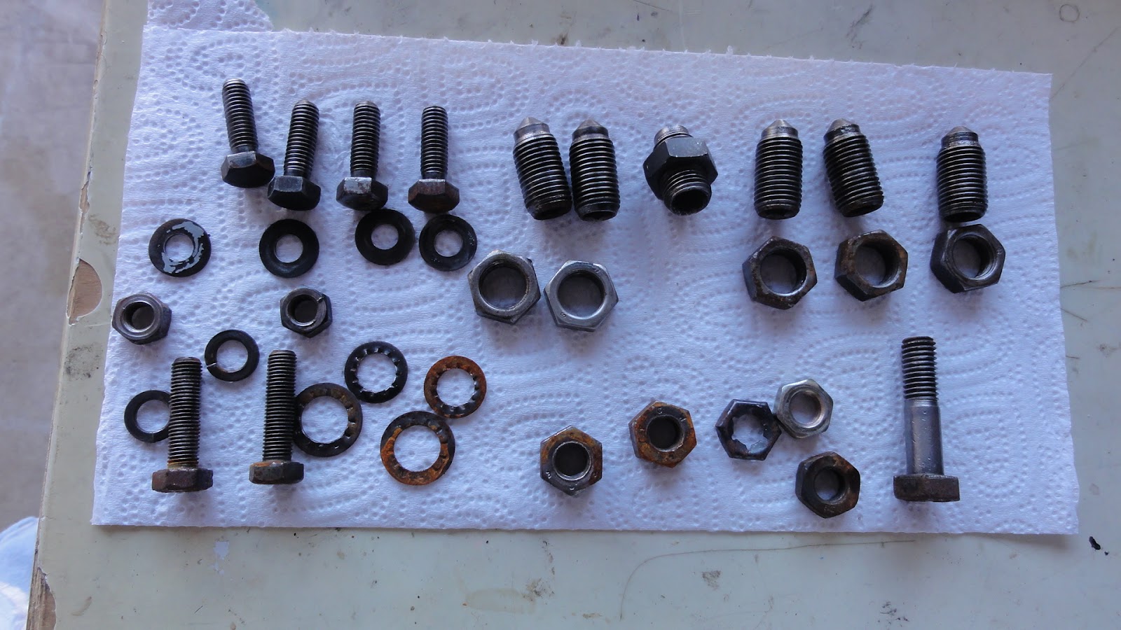
After that, the front beam, also freshly repainted, went back on, with the help of Valery and Madelaine.  Previously I had thought I could just paint the beam and leave a lot of the parts (like the nuts and locking screws) unpainted, but even though we've been in a drought, when it finally rained last month, all those unpainted pieces developed a fine patina of rust.

All the bits were painted
No more rust!
So, I had to carefully wire wheel and sand off all the rust then coated the entire beam with a fresh coat of hard gloss black paint.  I also cleaned up all the bits and pieces, painting them separately before putting them back on.  The end result was most impressive.  It really is starting to take on the quality of a rebuilt machine.  It's not a show car, but all the pieces are there, all painted and perfectly assembled.

Next: driveaxles, re-assembled and installed.

Wednesday, June 8, 2011

Trailing Arms


The frame is ready
The trailing arm is in.
There are parts of this process that I literally dream about, and many more that I simply think about all the time, but the task I completed yesterday was one I have been anticipating eagerly for the last couple of months in particular.  This was the replacement of the rear trailing arms.

With the new bushings pressed in, it was a simple, but time consuming matter of buffing off all the rust and dirt patina, priming, painting and re-installing.  The surfaces of the trailing arm are extremely complex, so I had to settle for getting most of the crud and minimizing the rest.  I also finished painting the rear torsion beam and all the mounts, so the frame was ready to receive the newly refurbished parts.

It looks good, right?
Well, it was installed wrong.
Of course, I had trouble recalling just how it went back together at first, so, the first thing I did was to put the left trailing arm in incorrectly.

However, thanks to this blog and the Xoom tablet, I was able go online and to find some pictures of what it looked like before I took it apart.  It turns out that the two big washers actually go next to each other (not on either side of the bushing as seemed logical) and the nuts (with the thin washers) go on the outside of the spring plate.

Back in, correctly!
How it looked when it came out...
Before...spring bolts.
After, spring bolts.
Having the 'before' picture is more than a nice device to show how much progress I've made.  It's also a good way of seeing how it is supposed to go without pondering the cryptic and woefully under-illustrated manual.  The manual will simply say, "remove/replace the bolts" while saying nothing about the direction it's supposed to go, or order of the washers.

Well, with the left side back in correctly, it was quite easy to put the right side in, all done before dark.

Before...trailing arm bolt.
After, trailing arm bolt.
As I have said, and will no doubt say again frequently as this thing comes together, this is a very satisfying part of the process.  Dreaming of the moment doesn't even compare to the pleasure I get when those nice clean parts fit into their places.

The nice part about this is that I have several more months of it to look forward to.

Next, it's back to the front end for some heavy metal.