Wednesday, July 25, 2012

It Runs!

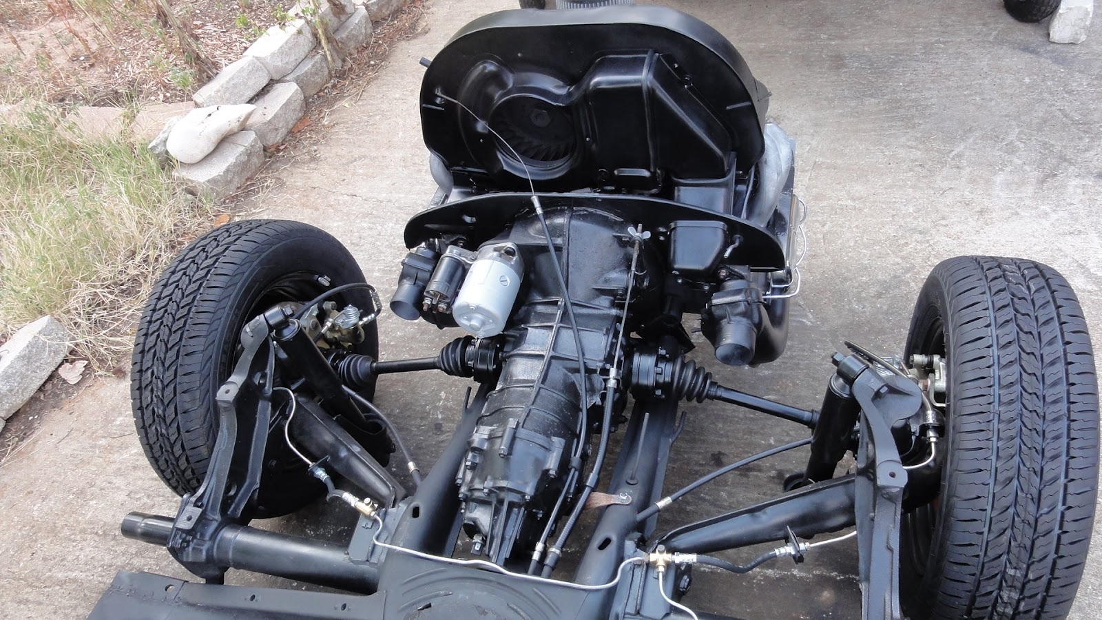
With the engine back on the chassis, it was time to see if it would run.  But first, there were some connections to be dealt with.

Fuel filter behind the engine.
Fuel line through the tin.
First I worked on the fuel system, attaching the hoses with clamps and routing the steel elbow line through the back tin.  I fixed the fuel filter in the line behind the engine tin, which is recommended but not what you see when you open up most VW engine compartments, because most folks are not concerned about the fire risk.

Fuel lines to the pump.
Fuel line at the front.
Thinking about how this car was essentially grounded because of an engine fire, I decided that this was an opportunity to make the change.  With the hoses hooked up to the fuel pump and carburetor on the engine side and the fuel line to the front of the car on the other side, that part was ready to go.

Wires ready to be hooked up.
A new battery.
Finally, in order to test the engine, I had to hook up the electrics.  Not all the wiring was needed, of course, but just enough to complete the circuit and get the engine to run.  This was one of the hardest tasks of all, mostly because I have trouble understanding the electrical diagrams, and partly because I don't have any wires to work with because they were all burned up.  So, I consulted The Samba and eventually figured out how to wire it up.

Starter is wired up.
Ready to start.
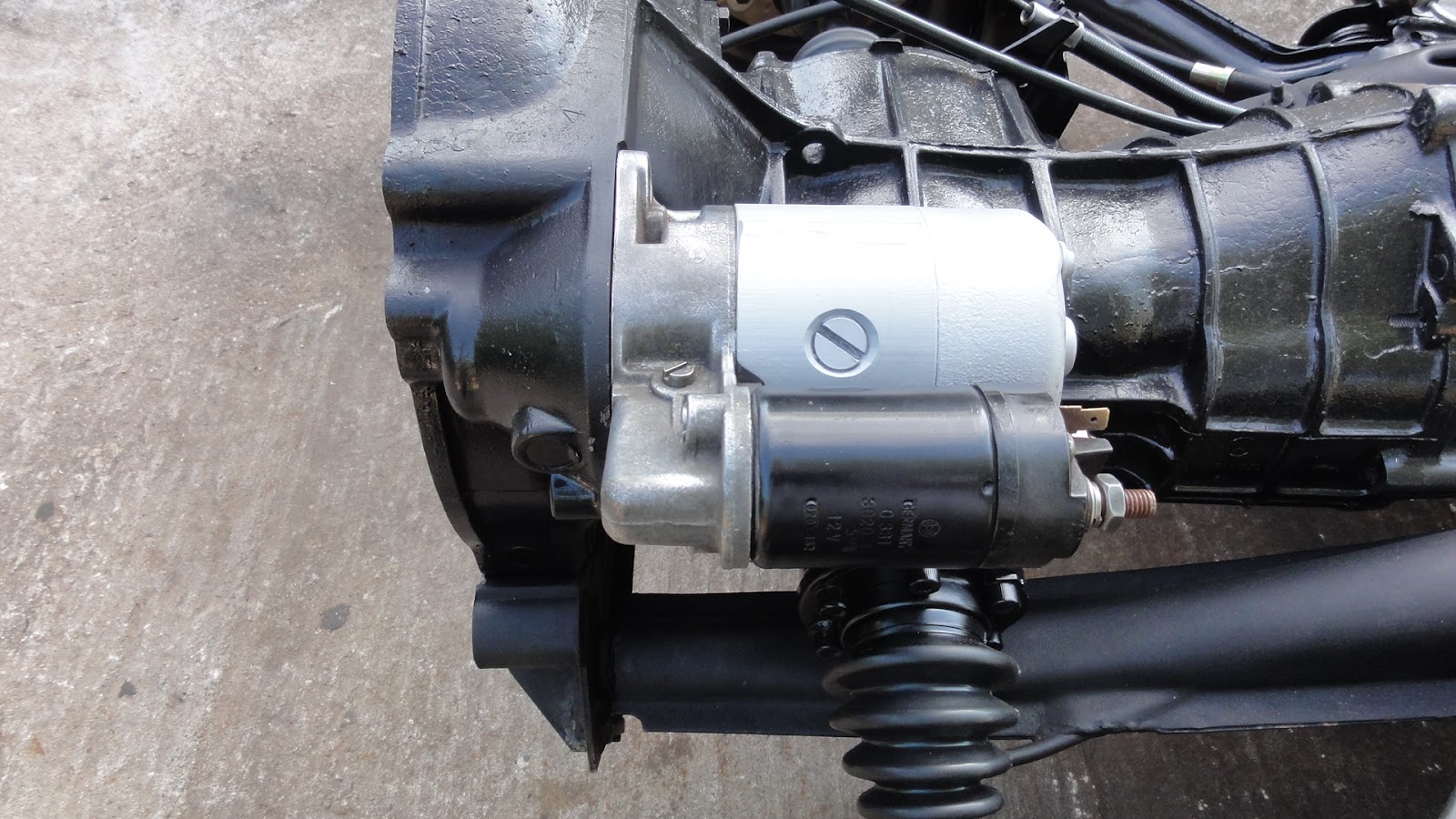
Weeks ago, I had already cleaned, painted and re-installed the starter, so now it was just a matter of hooking up wires between the starter, alternator, coil, distributor and battery.  I studied the diagrams, collected the wires and hooked them all up.  I bought a small gas can, put $1.00 worth of fuel in it and inserted a hose from the front end of the fuel line into the 'tank'.

Then I attempted to start the car.

Sputter and stop.
Wires are working.
First, some Good News.  What it did not do:  It did not scream, or grind, or howl or make any sort of mechanical noise that would make me think it was assembled incorrectly, or that some part was somehow loose inside the engine.  What it didn't do is as or even more important than what it did.

Oil is in the engine.
Now, I knew some of this already.  For example, I already knew that the engine would 'turn over'--that is, that it would go through the cycles without binding or crunching--because when I filled it with oil and turned it over by hand (with a big socket and breaker bar) to set the timing, nothing noticeable had happened.  I rightly took this to be a good sign at the time.  However, whether or not the engine would actually function without screaming or crunching under pressure was another matter.  This I could only determine once I was able to get it running on it's own.

But it sure didn't run.

More Good News.  What it did:  It 'fired', which means that I could see that the spark system was working.  I knew this because once I hit the starter 'switch' (actually me just touching the starter wire to the terminal) the engine would cough and sputter like it 'wanted' to run but somehow it just couldn't get going.

Now the Bad News.  This sputtering, it turns out, was only because I put a small amount of fuel into the carburetor to 'prime' it.  When I looked at the clear fuel filter between the tank and the pump, I could see that no fuel was passing through it.  This meant that the fuel pump wasn't working properly.

Or, I had hooked it up wrong.

Both readers know that the more likely scenario is that I have attempted to assemble it in the 'Phillip Way' and that something has been installed backwards, upside down or otherwise reversed from how it ought to be.  Indeed, this was the case.  I had installed the fuel lines in and out of the pump backwards, so of course no fuel was being pumped to the carburetor.

A quick switch of the lines proved this to true, and in a moment, I had fuel all the way up into the carburetor. By this time I had moved the 'tank' up to just behind the engine so I didn't have extra fuel sitting in the main line for months after I conduct this test and the engine is waiting for me to finish the body work.

Now the fuel lines are fixed.
With fuel now getting to the carburetor and a spark getting to the cylinders, it seemed more and more likely that I could get it running.  The biggest question that remained after 'solving' the fuel mystery was whether or not the carburetor was assembled properly.  I haven't yet described the process, but a few months ago I completely rebuilt the carburetor with a kit that I bought from JBugs.  The carburetor is one very complicated device, and even though I took it apart and re-assembled it, I have only the rudest notion of how the damn thing actually works.  Consequently I had little faith in my ability to get it all back together correctly and this in turn made it the weakest link in the attempt to get the engine running.

The only way to really test whether or not I had got the carb rebuild right was to try and start up the engine again.

So, I hooked up all the wires, double-checked the fuel lines, manually closed the choke on the carburetor (I have not hooked up the electric choke) and touched the starter wire to the battery.

Ready for a second test.
Once again, it coughed and sputtered and died.  But now I could see that it really ought to be working.  I could see all three elements of the internal combustion equation: spark, fuel and air, and I could see that it was really 'trying' to run.  The interesting thing about this engine is how forgiving it will be in getting started.  Now, it might not run right, and it might fail sooner than expected, but if you can just get close enough, the VW engine will run.  Anyone who's seen the clip from Woody Allen's Sleeper (or, amazingly, the whole movie) will know how universal this understanding is, and unlike so many urban legends today, it is actually true.

For proof of this assertion, I offer the following video:

Engine Back in Place

The whole reason for making the push and bearing the expense of getting the wheels and tires back on the chassis was to be able to mount and test the engine.

Chassis ready for the engine.
Just add engine to go!
While I could 'bench test' the engine on the ground--or at least mounted on a couple of two-by-fours--using just the most basic of wiring and fuel lines, I felt it would be better to mount the engine onto the chassis for this test.  Not only is the mounting hardware ideal for holding it in place, it will also allow me to test out the various linkages like the accelerator, clutch and fuel line.

Ready for those parts.
All the bits are here.
I dragged the engine out of the garage and laid out all of the pieces in the driveway.  All the various bits that I have already test-fitted at one point or another were brought out, including the engine tin, the coil and spark plug wires, the carburetor, the heater boxes and the muffler were ready to put on.

The starter looked rough...
...but it cleaned up nicely!
I also cleaned  up, repainted and re-installed the starter and solenoid combination on the back of the transmission.  Since I had no idea if it actually worked or not, I wanted to test this thing too, but figured the best way to do that would be to hook it up and see how it works.  The worst that could happen would be that it just won't work.

A lot of tin and part to go on.
All laid out.
I could say the same about the alternator, which I would love to have tested but really couldn't think of a better way to find out if it works than putting it in the engine and seeing if it actually works.  The problem with this approach is that it will be hard to tell if the alternator is actually doing it's job, charging the battery as it spins.  One thing is sure, if the engine doesn't run at all it could be the alternator, so I'll be testing that all at the same time.

This approach to testing is fraught with danger and the risk that something--likely something very small--won't work is very high.  This makes it a very complicated test environment.   I am going to be testing to see if half a dozen new, rebuilt or just replaced parts have been put back together correctly.  Given that this process has been guided by someone who only sort of knows what he is doing, it's very likely that it won't start, won't run, or worse, break.

The heater boxes and muffler.
Everything lines up.
Before putting the engine back on the chassis, I also had some final assembly to take care of on the engine.   Most of the bits had been put back on while it was on the table, but once I moved it to the dolly and was waiting for the tires and wheels, I left a lot of parts that could have gone on the engine off of it, just to make the transition easier.

The heater flap control rod...
All hooked up.
I started by putting the fan shroud with the alternator back over the oil cooler and attached it to the block.  Then, after tightening the alternator strap, and attaching the transmission ground strap, I put on the heater flap control rod, hooked up all the spark plug wires and routed them through the new mounts on the fan shroud.

The transmission ground strap
Things like the heater boxes and the muffler were much easier to put back on with the engine out in the driveway.  These big pieces, plus lots of the engine trim--especially the pieces that go below the pushrod tubes and attach to the heater boxes--went back on without much trouble.  The hardest part is connecting the bottom pieces of tin.   I had to leave this task until I had the engine up on the chassis so I could actually reach the mounting holes with a screwdriver.

With the major bits back on the engine,  it was time to put it back in place.

Getting the engine back on the car was actually a very easy job.  In fact, I did it by myself in just a few minutes.  In fact, it went so quickly that I didn't even get any good pictures.  I brought the engine up as close to the chassis as I could get it on the dolly, then placed the two jacks under the heater boxes.

The engine is in!
Ready to run?
I jacked it up slowly until the transmission shaft was lined up with the clutch, wiggled it a bit to get the engine mounting studs into the holes on the transmission, then, with a gentle but confident push, I shoved it onto the shaft.  I slid in the engine mounting bolt on the starter, and put the two bit nuts on the studs at the bottom.  A few turns and it was secure enough to pull away the jacks.

Next, it is time to test the engine!

Thursday, July 5, 2012

Pedals, Brakes and Wheels

With the rear brake lines finally fitted with the new custom brackets, I turned my attention to two other areas of concern; the pedals and the wheels.

Missing pedal stop
The missing piece
The pedals had been refurbished after purchasing the set used at Austin VeeDub.  I went to install them a couple of weeks earlier, but discovered that they would not stay in a resting position because I was missing a part.  This was the pedal stop, a two dollar piece of steel with a hole for a bolt and a curved lip to keep the pedal set from flopping backward when released.

Hole drilled in the pan
Bolt up through it...
The reason I missed it was because the original piece was on the rusted out floor pan, and I think I threw it away.  I don't recall seeing it and it isn't in any of the early pictures, so it may have been missing.

...and the pedal stop is in.
Stopping the pedals...
In any case, it can be hard to catch something you didn't know was supposed to be there, but it was an easy and inexpensive fix.  I ordered the part and installed it in a few minutes.  I drilled a hole in the floor pan where the bolt was supposed to go, then slipped it up through the bottom side.  I used some epoxy to hold the bolt head in place and mounted the stop with no trouble.  Then, with the accelerator and clutch cables connected, the whole assembly fit together perfectly.

Drag out the wheels...
...and buff 'em and paint 'em
The next step was to get the car back on its wheels and tires.  What I really wanted to do next was to put the engine back on the car so I could test it, but I knew this couldn't happen until I had the wheels and tires back on because I knew the weight of the engine made it more likely to tip over on the jack stands that had held the chassis for over a year.  I just didn't want to risk the whole thing falling on the ground.

That lovely VW mark
The wheels were a bit of a rusty mess.  I had the tires removed many months ago, to make the storage easier.  I stuck the wheels up under the chassis, so if they weren't rusty when I put them there, they were when I took them out.  It was all just surface rust and a lot of grime.  I set to work cleaning the wheels and this was one of the most labor-intensive jobs I had on the car so far.  I must have spent at least two hours cleaning, buffing, blasting, sanding and painting each wheel.  This was a tedious and particularly boring job, and if it hadn't been for the vision of the car finally back on a set of tires, I might not have done it.  I kept my shoulder to the wheels, so to speak, and in about two weeks I had them ready for tires.

First wheel goes on
Polish the old hubcaps
Tires were a bit of a problem.  Originally I envisioned buying a set of used tires just to put the car back on the ground.  Figuring it would be another year at least, I thought I could wait to buy a new set of rubber when I was ready to put the body back on.  Well the best laid plans never work out.  In fact used tires for an old VW are nonexistent because they are just not on the road in the numbers they used to be.  So, I had to figure out a way to buy a new set.  This wasn't easy because at this point I have just about run out of money.  I sure didn't have the $300 needed to go get my shiny clean wheels clad in fresh rubber, but I couldn't wait any longer.  So I went to Walmart and bought a set of tires on credit, putting $100 down and planning to pay of the balance at $50 a month.  I had my tires that afternoon, and in a few short minutes, I had reached a major milestone.

The Ghia was back on her feet.

Voila!  A rolling chassis
Next I had to finish the brake system.  Two major pieces were now missing, the front-to-back hard line and the brake fluid reservoir.  The former was relatively easy.  I had the part and it was just a matter of bending it into the right shape and hooking it up.  Like the other lines, it was a little long, but a little looping at the end made it all fit.  I went around and tightened all the fittings again, just to make sure they wouldn't leak when pressure was applied.

Front-to-back brake line
Under the pedals
But before I could apply any pressure to the brakes, I had to fill the lines with fluid.  And to do that, I had to install the brake fluid reservoir and the hoses that connect it to the master cylinder.  This wasn't easy because the the bracket onto which the reservoir properly mounts is actually on the body, up under the hood.  So I needed a temporary bracket to mount it, and this meant making one from scratch.

Cardboard template
It's the wrong size...too short
Like my brake line brackets, this one started with a cardboard template.  I measured it, cut it out and bent it into shape.  I figured out a way to mount it to the floor using one of the drain holes already in it and put it in.  Right away, I found out that my design was flawed.  The bracket was too low and it caused the hoses to buckle.

New bracket and reservoir mounted
This time it fits
This wasn't going to work, so I re-designed the bracket, cut it out and installed it.  This one, about six inches taller, worked perfectly.  I hooked up the hoses and mounted the reservoir to the bracket with a simple screw and a wire harness.  It looks a bit goofy, but it's only temporary after all.

Next, it's time to put the engine back on the chassis.

Thursday, June 28, 2012

Rear Brake Line Brackets

Time for brake lines
With the engine nearly done and ready to go back in the car, it was time to turn my attention back to the chassis.  For one thing, I can't put the engine back on to the chassis until I put the car back on its wheels and tires.  And I can't do that until I clean and paint the wheels.  I also have to buy some tires, and for the time being, I am out of cash, so that will have to wait.

In the meantime, there are plenty of things that I can work on that won't cost me anything and don't involve the engine.  Like the rear brake brackets, for example.

These brackets don't exist.  Or at least, they didn't until I fabricated them.  The reason I had to make them was because I installed a set of disc brakes on the rear, where the standard drum brakes had been, so the brake line configuration had to change.

In the old arrangement, the rear brake lines consisted of two parts: 1) a soft, flexible hose that went from the hard line junction on the chassis to a bracket on the trailing arm; and 2) a hard stainless steel brake line that went from that bracket/hose connection directly into the brake cylinder on the drum housing.

With the drum brake removed, the configuration became much more complicated because the disc brake has a flexible line coming out (instead of a hard line) and it emerges from the back and bottom of the caliper set, which is about eighteen inches longer than the original distance.

So now I have a double hose (consisting of a long and a small piece) and no place for that hose to connect to the hard line.  In words this sounds confusing and even in 'real life' it was not much easier.  I scratched my head for months after installing the calipers, figuring I would just have to figure it out when the time came.

Tapping the hole on the trailing arm
Well the time had come.  I looked carefully at the trailing arm and discovered that there were two small holes in it just at the point where the big rubber stop (which prevents the trailing arm from hitting the body with too much force) is mounted.  I realized that if I tapped one of those holes, it would be the perfect place to mount the bracket.

Now, the bracket has to have two holes in it.  One is large enough to allow the hose connector to pass through, but not large enough to allow the whole hose through.  Once the hose connector is in this hole, the bracket clip slides down into a slot between the bracket and the connector.  The other hole is small, used for the mounting bolt.  The whole thing can't be very big or it will get in the way, and it can't be too flimsy or it will bend and the brakes will fail.

The first prototype out of paper
Drilling the first hole
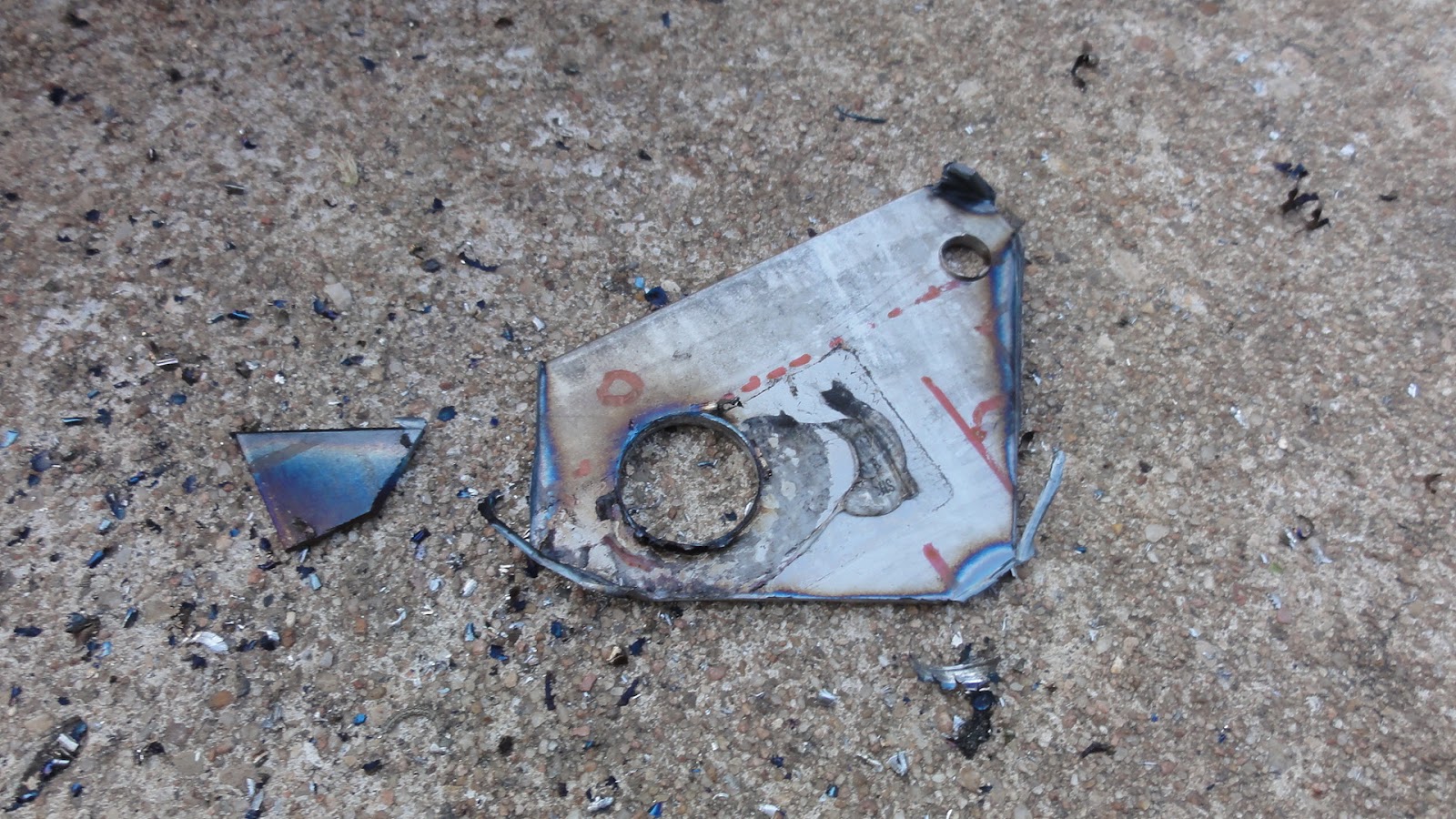
I started out with a piece of paper.  I drew what I thought would be the correct shape and cut it out.  Amazingly, my very first paper piece looked like it would work, so I set about to make it in steel.  I had a very thin piece of steel that I used to practice my welding on.  I bought it from a scrapyard, thinking it was about the same thickness as the sheet steel in the body, but it proved to be much thinner than that, so I set it aside.  Now it seemed like it would be just the right thickness, so I traced the paper template on the steel sheet and cut it out with a a high-speed cutting tool.

Several versions were required
Step drill bits that almost worked
One of the very first problems I encountered was the size of the big hole.  I measured the connector and  found I would need a hole no smaller than 9/16.  This meant I would have to buy a special bit of that size, since 1/2 inch was the largest bit that I could find in a reasonably priced set.  A 9/16 bit cost over $15, which is at least double what a new set of carbon-tipped bits (with sizes ranging from 1/16 all the way up to 1/2 inch) would cost.  And I only needed it to drill two holes.

Version #4
The compromise was to buy a step-bit set for about $8.  This three bit set looks like a stepped cone, and the idea is that it will drill holes of any size, one step at a time.  You start small and gradually the hole gets to the size you need.
The hole is first

This is the idea, but in practice, the bit heats up and fails as you get into the larger sizes, rendering the bit useless long before even one hole of the proper size has been drilled.  Eventually I decided to go ahead and buy the carbon-tipped set that included the 1/2 inch bit and use that and a file to get my 9/16 inch sized hole.

The piece is cut out
The raw piece
Compounding the bit problem was the fact that it turned out that it wasn't just to drill two holes.  Because I was going to have to fabricate several brackets as I honed in on the correct size and shape, it meant that I was going to have to drill a bunch of these big holes and the drill bits just couldn't keep up.

Eventually, however, I managed to make two holes of the proper size, but first I had to cut out, shape and bend at least five different versions of the bracket before I had one that I knew was going to fit and not fail.

Mounted, #4 is too big
Starting on #5
One key factor was the thickness of the steel.  I bought a piece of steel at Home Depot for about $9 and even though it was a lot thicker than my first piece of scrap steel, it was still too thin.  I couldn't find a piece of steel at Home Deport that was any thicker, so I settled on using a bit of the thinner steel as a shim.

Both raw brackets and shims
The bracket and shim in place
This meant cutting out two small squares of thin steel, drilling 9/16 inch holes in them, then placing those shims on the bracket with some epoxy.  Though complicated, actually worked, and eventually I had not only the proper shaped brackets, but the shims and bolts in place.  The connection is solid and secure, and it even looks like it was meant to be there.

Loopy lines
They look goofy but work
Unfortunately, the arrangement is not as neat as I hope it would be.  This is not because of the brackets, but because the brake lines that came in the kit I bought were just a bit too long.  This meant I had to bend them in some rather unusual ways, creating a kind of loopy look that will work but sure doesn't look stock.  Even though that wasn't the intention, if it works I will be happy with it.

Next up I have to install the front-to-back brake line, install the brake fluid reservoir on a temporary bracket (it's actually supposed to be mounted on the the body), fill the system and bleed the brakes.